
BENEFIT
TECHNICAL DATA
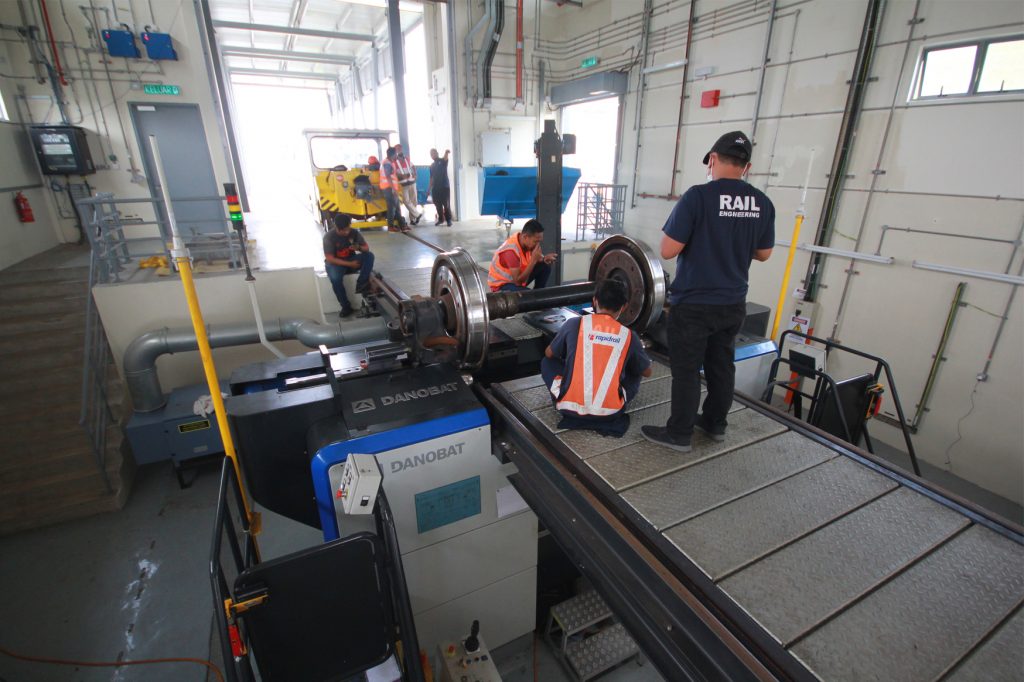
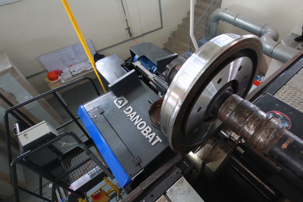
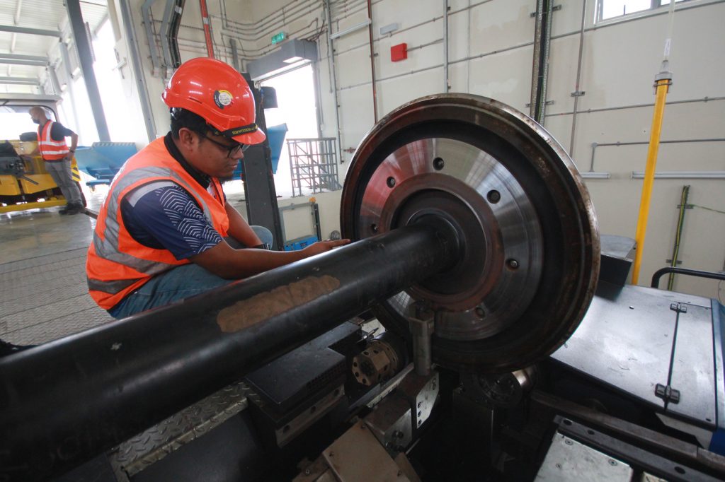
EQUIPMENT
BENEFIT
BENEFITS
- UWL range for all vehicle types:
- Tram
- Metro
- Commuter
- High Speed
- Locomotive
- Fully automatic machining process
- Smart machining: reduces cycle time, increases the process reliability and safety and extends the life of the wheels within a railway fleet.
- Conceived to operate with only one operator
- Ease of use: User-friendly interface for an intuitive operation that assists the operator and helps in optimizing machining processes.
- Optimized layout and pit configuration
- Designed for best ergonomics and ease of maintenance.
TECHNICAL DATA
TECHNICAL DATA
| DLR | DHD | DHD+ | ||
| WHEELSET CHARACTERISTICS | ||||
| Track gauge | mm | 1000 to 1676 | 1000 to 1676 | 1000 to 1676 |
| in | 39.5 to 66 | 39.5 to 66 | 39.5 to 66 | |
| Wheel Ø | mm | 350 to 1250 | 350 to 1250 | 350 to 1250 |
| in | 14 to 49.5 | 14 to 49.5 | 14 to 49.5 | |
| Profile width | mm | 75 to 150 | 75 to 150 | 75 to 150 |
| in | 2.95 to 6 | 2.95 to 6 | 2.95 to 6 | |
| MACHINE CHARACTERISTICS | ||||
| Main drive power | kW | 4×9 | 2×30 | 2×30 |
| hp | 5×12 | 3×40 | 3×40 | |
| Chip section | mm2 | 6 | 10 | 10 |
| in2 | 0.009 | 0.015 | 0.015 | |
| MACHINE ARQUITECTURE | ||||
| Single | — | √ | √ | √ |
| Tandem | — | √ | √ | √ |
| Variable track gauge | — | √ | √ | √ |
EQUIPMENT
EQUIPMENT
Clamping Solutions
A) Externally mounted axle-boxes
B) Internally mounted axle-boxes
C) Between Centres

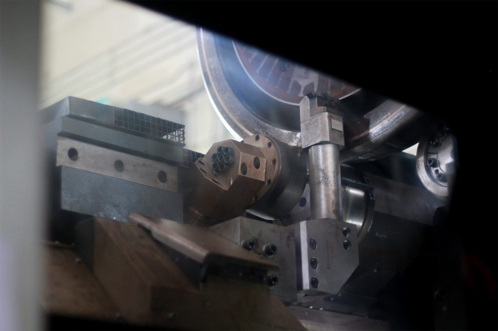
Turning
1) Wheel Profile
2) Internal faces
3) External faces
4) Wheel mounted brake-disc facing
5) Axle mounted brake-disc facing
6) Wear grooves
